

ANSI/CTA 2034-A 2015 Measurements
A test sequence to measure the peak full range (maximum) sound pressure level of a loudspeaker to the ANSI/CTA 2034-A 2015 standard

Figure 1 – Final display results – ANSI/CTA 2034-A 2015
Introduction
This sequence determines the maximum output capability of an in-home full-range loudspeaker system to the ANSI/CTA 2034-A 2015 standard.
This standard uses shaped noise bursts and limits to measure the maximum output of a speaker with regards to performance, rather than simply the maximum physical output. For full setup information, please refer to the standard available for purchase here. This standard is designed for full range loudspeakers. For maximum output of subwoofers please see the SoundCheck sequence based on ANSI/CEA 2010-B 2014 available here.
Section 8.2 of the standard describes how to calculate on-axis maximum usable Sound Pressure Level – Peak. The signal is a 1/3 rd Octave band limited tone burst that is presented to the loudspeaker at ISO 1/3 rd octave frequencies between the range of 20Hz to 5kHz. At each test frequency, the tone burst is sent to the device under test, increasing in 3dB increments until the peak exceeds the limits specified in the standard. Once the limits are exceeded, the signal is decreased by 3dB and the level increments 1dB at a time until the limit is exceeded again. This level is recorded as the maximum for that frequency and the test repeats at the next ISO 1/3 rd octave frequency point.
The peak SPL values are weighted according to the power spectrum defined in the standard and the Average Weighted SPL is calculated by averaging the weighted values from 100 Hz to 5 kHz. A series of calculations are then applied to the test data to produce the final Broadband Peak SPL value.
Note: ONLY open “ANSI+CTA 2034-A.sqc” in SoundCheck. All other sequences and files included in this package are called from this sequence and must remain in the same directory as “ANSI+CTA 2034-A.sqc”.
Software Requirements
- SoundCheck Plus Version 22 or later Part # 1102
Hardware Requirements
- AmpConnect 621 or similar Part # 4046
- Measurement Microphone – Listen SCM or similar Part # 4002
Hardware Setup & Calibration
- Before opening the sequence, in SoundCheck select Setup > Calibration > Import. Select the
“System.cal” file in the unzipped folder - Assign signal paths “Mic 1” and “Amp 1” to the appropriate hardware channels.
- Calibrate the microphone signal path “Mic 1” as instructed in the SoundCheck manual.
- Calibrate your amplifier signal path “Amp 1” as instructed in the SoundCheck manual
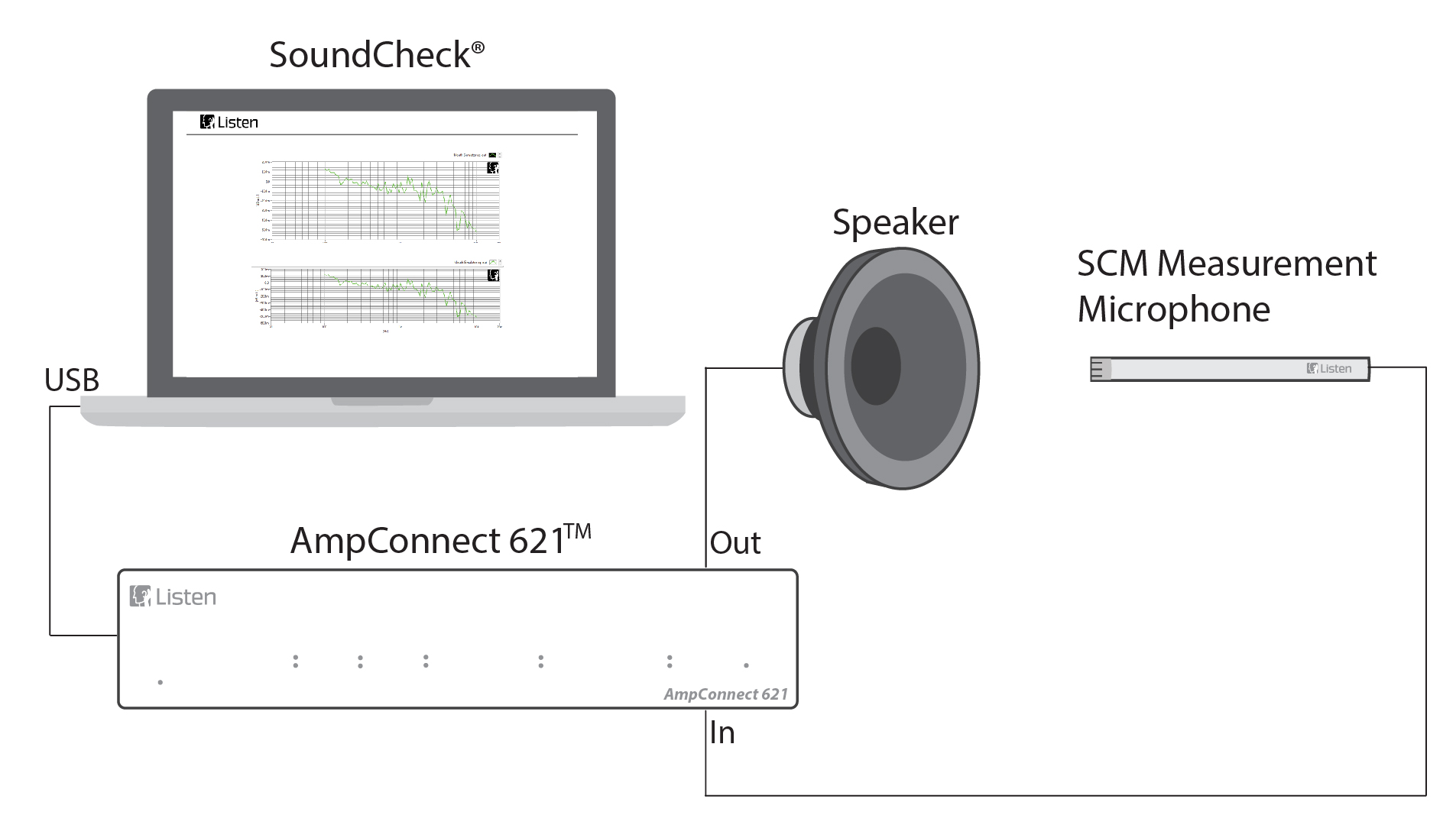
- Connect your amplifier output to your loudspeaker.
- Place the microphone 1 meter from the loudspeaker in a calibrated anechoic chamber, suitable ground plane environment, or large calibrated room according to the standard
- Open the sequence “ANSI+CTA 2034-A.sqc”. All other sequences and files MUST remain in the same directory as this sequence but should not be opened directly.
You are ready to start the sequence.
System Diagram for measurement to the ANSI/CTA 2034-A 2015 standard
Further sequence development
Ways in which you could modify or further develop the sequence include:
- Autosave steps can be added in between measurements within the sequence, or at the end of the sequence.
Get Sequence
Download ANSI/CTA 2034 Test Sequence (zip file)
Download ANSI/CTA 2034 documentation (PDF)


